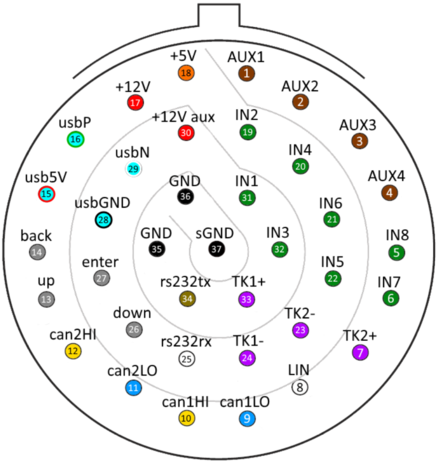
SDM-700 PINOUT and FUNCTIONS
|
|
|
SDM 700 PIN FUNCTIONS - PLUG A
|
|
|
NO
|
LABEL
|
Description
|
Notes
|
|
1
|
AUX1 HS
|
Auxiliary output – High Side 3A
|
ON/OFF or PWM.Sources current from pin 30
|
|
2
|
AUX2 HS
|
Auxiliary output – High Side 3A
|
ON/OFF or PWM.Sources current from pin 30
|
|
3
|
AUX3 LS
|
Auxiliary output – Low Side 1A
|
ON/OFF or PWM.Sinks current to GND
|
|
4
|
AUX4 LS
|
Auxiliary output – Low Side 1A
|
ON/OFF or PWM.Sinks current to GND
|
|
5
|
AN8 / DI8 / FR8
|
Analog/Digital/Frequency input 0-16V,selectable pull down 330Ohm
|
|
|
6
|
AN7 / DI7 / FR7
|
Analog/Digital/Frequency input 0-16V,selectable pull down 330Ohm
|
|
|
7
|
TK2+
|
Type-K thermocouple input 2, positive
|
|
|
8
|
LIN
|
Lin bus Master connection
|
|
|
9
|
CAN BUS 1 LO
|
250kbit – 1.333Mbit speed, selectable 120R termination
|
|
|
10
|
CAN BUS 1 HI
|
|
|
|
11
|
CAN BUS 2 LO
|
250kbit – 1.333Mbit speed, selectable 120R termination
|
|
|
12
|
CAN BUS 2 HI
|
|
|
|
13
|
SW3-UP
|
Control button input for UP command
|
The other terminal of the button should be connected to GND
|
|
14
|
SW2-BACK
|
Control button input for BACK command
|
The other terminal of the button should be connected to GND
|
|
15
|
USB-5V - red
|
PC Comms usb cable 5V connection
|
|
|
16
|
USB DATA-P - green
|
PC Comms usb cable data positive connection
|
|
|
17
|
+12V
|
Power supply for the device. 9-18V. Max 1A
|
Connect to a switched +12V power source.
|
|
18
|
5V
|
5V sensor supply. Max 200mA
|
|
|
19
|
AN2 / DI2 / FR2
|
Analog/Digital/Frequency input 0-5V,selectable pull up 1KOhm
|
|
|
20
|
AN4 / DI4 / FR4
|
Analog/Digital/Frequency input 0-5V,selectable pull up 1KOhm
|
|
|
21
|
AN6 / DI6 / FR6
|
Analog/Digital/Frequency input 0-16V,selectable pull down 330Ohm
|
|
|
22
|
AN5 / DI5 / FR5
|
Analog/Digital/Frequency input 0-16V,selectable pull down 330Ohm
|
|
|
23
|
TK2-
|
Type-K thermocouple input 2, negative
|
|
|
24
|
TK1-
|
Type-K thermocouple input 1, negative
|
|
|
25
|
RS232-RX
|
RS232 data input
|
|
|
26
|
SW4-DOWN
|
Control button input for DOWN command
|
The other terminal of the button should be connected to GND
|
|
27
|
SW1-ENTER
|
Control button input for ENTER command
|
The other terminal of the button should be connected to GND
|
|
28
|
USB-GND - black
|
PC Comms usb cable ground connection
|
|
|
29
|
USB DATA-N - white
|
PC Comms usb cable data negative connection
|
|
|
30
|
+12V AUX
|
Power supply for AUX1 and AUX2. 9-18V. Max 6A.
|
Connect to a switched +12V power source.
|
|
31
|
AN1 / DI1 / FR1
|
Analog/Digital/Frequency input 0-5V,selectable pull up 1KOhm
|
|
|
32
|
AN3 / DI3 / FR3
|
Analog/Digital/Frequency input 0-5V,selectable pull up 1KOhm
|
|
|
33
|
TK1+
|
Type-K thermocouple input 1, positive
|
|
|
34
|
RS232-TX
|
RS232 data output
|
|
|
35
|
GND
|
Ground supply
|
Connect both the chassis ground.
|
|
36
|
GND
|
Ground supply
|
|
|
37
|
SGND
|
Ground supply for sensors
|
|