i44
SDM-500 pin 5 CAN1 HI yellow -------------> Vipec Communications Connector pin 3 CAN H
SDM-500 pin 4 CAN1 LO blue -------------> Vipec Communications Connector pin 4 CAN L
i88
SDM-500 pin 5 CAN1 HI yellow -------------> Vipec Communications Connector pin 3 CAN H
SDM-500 pin 4 CAN1 LO blue -------------> Vipec Communications Connector pin 4 CAN L
|
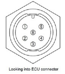
Pin
|
Colour
|
Function
|
|
1
|
Brown
|
Ground
|
|
2
|
Blue
|
NC
|
|
3
|
White
|
CAN H
|
|
4
|
Green
|
CAN L
|
|
5
|
Yellow
|
ECU RS232 TX
|
|
6
|
Gray
|
ECU RS232 RX
|
|
Setting up the Vi-PEC ECU:
|
|
|
|
|
|
|
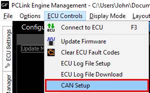
1.
|
Open the CAN Setup window (iVTS > ECU Controls > CAN Setup)
|
|
|
|
|
|
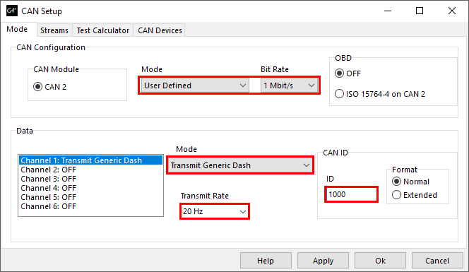
2.
|
Select the CAN module to be used
|
|
|
|
|
|
3.
|
Set the Mode to 'User Defined'.
|
|
|
|
|
|
4.
|
Configure the Bit Rate to 1 Mbit/s
|
|
|
|
|
|
5.
|
Select a spare CAN channel.
|
|
|
|
|
|
6.
|
Select 'Transmit Generic Dash' from the Mode drop-down menu.
|
|
|
|
|
|
7.
|
Set the CAN ID to match the ID the dash is configured to. (1000)
|
|
|
|
|
|
8.
|
Set the Transmit Rate to match what the dash expects.
|
|
|
|
|
|
9.
|
Make sure no other CAN channels are configured on the same CAN ID as the Generic Dash channel.
|
|
|
|
|
|
10.
|
Click Apply and then OK.
|
|
|
|
|
|
11.
|
Make sure a Store (F4) is performed.
|
|
|
|
|