QUICK INFO:
This optional installation step is necessary when one wants to connect the Plex Knock Monitor either to an ecu, a dynamometer or an external warning light.
ANALOG OUTPUT
CONNECTOR
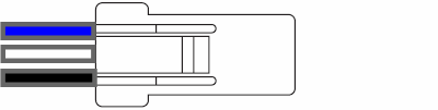
blue: Analog output 2
white: Analog output 1
black: Analog output ground
For each of the 2 outputs 7 different functions can be selected in menus 4.2 and 4.3.
1. Knock Level from Sensor 1
The voltage level will reflect the current signal level from knock sensor 1.
Level 0 = 0V, Level 255 = 5V
2. Knock Level from Sensor 2
The voltage level will reflect the current signal level from knock sensor 2.
Level 0 = 0V, Level 255 = 5V
3. Knock Level maximum from Sensor 1 and Sensor 2
The voltage level will reflect the whichever signal level is higher between knock sensors 1 and 2.
Level 0 = 0V, Level 255 = 5V
4. Knock Threshold
The voltage level will reflect the current knock detection threshold.
Level 0 = 0V, Level 255 = 5V
5. Knock Count Total
The voltage level will reflect the total count of detected knock events from all cylinders.
The output resolution is approximately 20mV per event.
6. Knocking Cylinder
The voltage level will reflect the last cylinder that a knock event was detected for.
Cylinder 1: 0.63V
Cylinder 2: 1.25V
Cylinder 3: 1.88V
Cylinder 4: 2.50V
Cylinder 5: 3.13V
Cylinder 6: 3.75V
Cylinder 7: 4.38V
Cylinder 8: 5V
7. Knock Ignition Retard
The voltage level will rise according to the level of knock detected. When no knock is detected the voltage will slowly ramp down.
An ecu can be configured with a function to retard 1-2 degrees of ignition advance per 1V measured on an analog input.
8. Knock Warning
This is a 2 state output function. 5 Volts are output when knock is detected and 0 Volts when not.