QUICK INFO:
This optional installation step is necessary when one wants to detect knock using a variable noise threshold vs rpm, knock per cylinder, or both.
Depending on convenience and preference there are 5 alternative connection points for getting trigger signal. For knock/rpm any of the
5 options can be used, whereas for knock/cylinder only options C, D & E are suitable.
TRIGGER INPUT
CONNECTOR
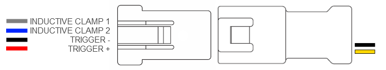
red: trigger positive input
black: trigger negative input
blue: inductive clamp input 1
grey: inductive clamp input 2
The trigger extension wire will have a yellow wire for trigger positive and a black wire for trigger negative.
The yellow wire should be connected using one of the options A,B,C,D and E bellow.
The black wire should alway be connected to engine ground.
CAUTION!
For detecting knock using 2 knock sensors(only for dual input Knock Monitor versions) it is required to connect the trigger input to the ignition signal of cylinder 1 and
to configure the firing order and cylinders sensor assignment correctly.The device will not work properly otherwise.
A. INJECTOR OUTPUT
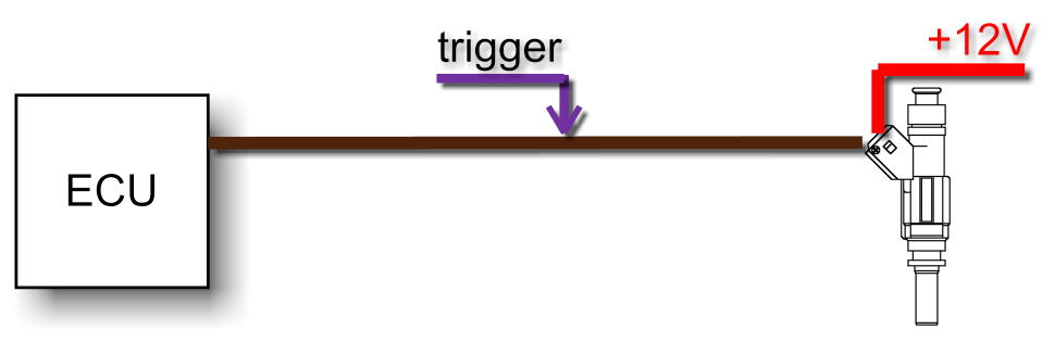
Required Action
- Select FALLING edge in menu 3.3
Hint!
Only works with saturated injector drivers, not peak and hold type.
B. TACHOMETER OUTPUT
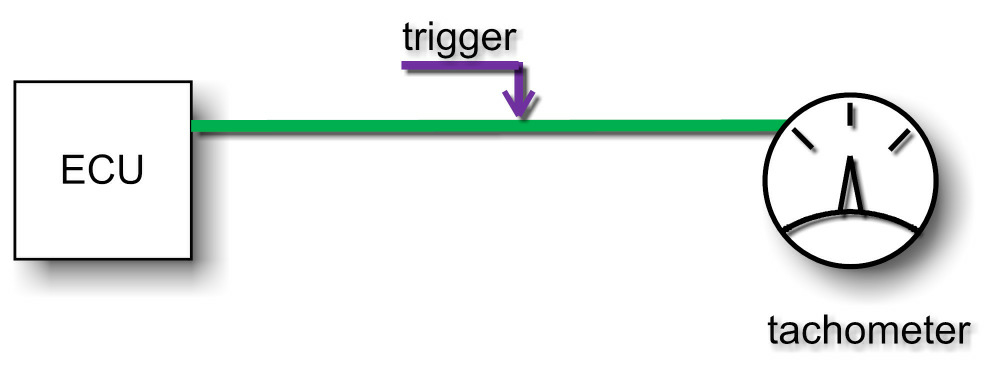
Required Action
- Select any edge in menu 3.3
C. ECU WITH INTERNAL COIL DRIVERS
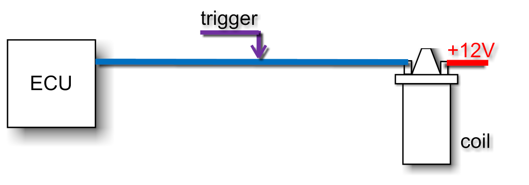
Required Action
- Select RISING edge in menu 3.3
D. ECU WITH EXTERNAL COIL DRIVERS
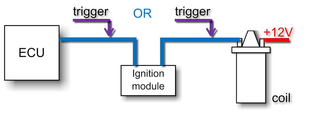
Required Action
- Select FALLING edge in menu 3.3 when connecting to th ecu side, or RISING when connecting to the coil side of the ignition module
E. ECU WITH CAPACITIVE DISCHARGE IGNITION
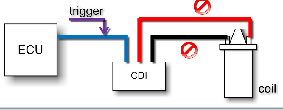
Required Action
- Choose edge according to the CDI trigger pulse
Attention!
- Connect the trigger inputs ONLY to the ecu side, NEVER to the coil side
- For per cylinder knock detection the trigger input has to be connected to the number "1" cylinder signal